

Cantilever Shoring

Typically used when the vertical face of the excavation is less than 20 feet, cantilever shoring consists of soldier piles and lagging. Soldier piles are constructed with steel I-beams. Wood or steel plate lagging is then placed between the I-beams to hold the earth in place.
Internally Braced Shoring
Internally braced shoring systems consist of soldier piles, lagging and internal braces. The internal braces are rakers or struts. Rakers are structural members that diagonally brace the vertical walls by transferring the load to the bottom of the excavation. Struts are placed between the two sides of the excavation so that they brace each other. Internally braced shoring systems can be constructed to depths approaching 100 feet. Internally braced shoring systems are useful when there are property line and utility boundary concerns.
Secant Pile Wall Shoring

Continuous Flight Auger (CFA) equipment is employed to construct a secant pile wall. Simply put, secant piles are overlapping concrete piles that form a strong, watertight barrier. On the first day of drilling, “soft” piles are drilled in predetermined spots. On the following day, “hard” piles are drilled in between the soft piles. These piles actually core into the soft piles on either side of them. The hard piles are made of high strength concrete, and are often reinforced with steel I-beams or cages.
The end result is a continuous intersecting line of concrete piles that can be placed before any excavation is performed. Secant pile walls are frequently constructed in closed shapes to form cofferdams.
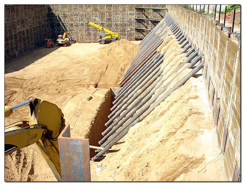
Soldier Pile and Tieback Shoring

Tiebacks may be used in conjunction with soldier piles to replace the bracing elements of internally braced shoring systems. Tiebacks are constructed by drilling a small diameter shaft into which a steel reinforcing member is inserted. Grout is then pumped into the shaft surrounding the tieback steel. After curing, the whole assembly is stressed by a hydraulic jack and locked off at specified design loads.
Numerous rows of tiebacks may be required depending on the depth of the excavation. Tieback technology provides for an unlimited depth of excavation. Property and utility lines in close proximity to the excavation can be a concern to horizontal tieback drilling.
Soil Nail Shoring
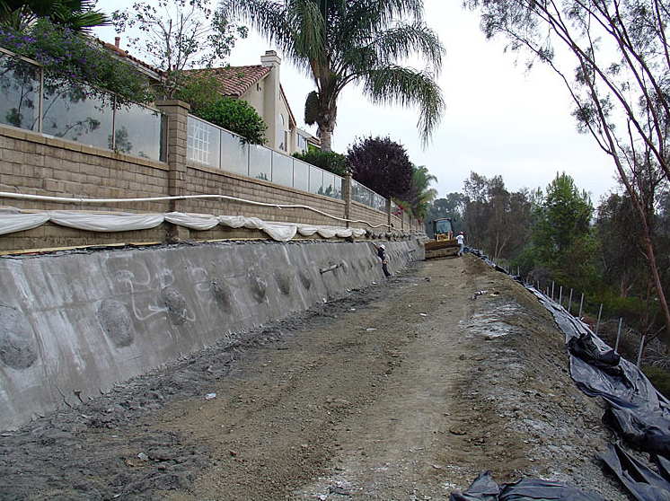
Similar to tiebacks, soil nails are installed in rows across the excavation’s face. The number of soil nails per row is dependent on earth conditions and design loads. Soil nail shoring systems include steel bars grouted in place with cement. Steel reinforcing mesh is laid over the face of the excavation connecting the steel bars together. 3000-4000 psi concrete is then sprayed over the mesh in the form of shotcrete.
In general, this process is repeated in 4' to 6' intervals until the depth of the excavation is reached. Depending on the types of soil, soil nail shoring systems can be constructed to depths of 100 feet.


